Suche
12 Ergebnisse gefunden

GCVR 300 T für I/O Box
… Product Liability … 5 Product description … 8 Technical data … Product Liability Gemäß der im Produkthaftungsgesetz definierten Haftung des Herstellers für seine Produkte sind die in dieser Anleitung enthaltenen Informationen (Produktinformationen und bestimmungsgemäße Verwendung, Fehlgebrauch, Produktleistung, Produktwartung, Informations- und Instruktionspflichten) zu beachten. Die Nichtbeachtung entbindet den Hersteller von seiner Haftungspflicht. Bei Kombination mit Fremdgeräten übernimmt GEZE keine Gewährleistung. In accordance with the manufacturer's liability for its products as defined in the Product Liability Act, the information contained in this manual (product information and intended use, misuse, product performance, product maintenance, information and instruction requirements) must be observed. Failure to observe releases the manufacturer from his liability. When combined with third-party devices, GEZE assumes no guarantee. Hinweis: Note: Das Produkt sollte so eingebaut oder verbaut werden, dass ein müheloser Zugriff auf das Produkt bei etwaigen Reparaturen und/oder Wartungen mit verhältnismäßig geringem Aufwand gewährleistet ist und etwaige Ausbaukosten nicht in einem Missverhältnis zu dem Wert des Produktes stehen. The product should be installed or installed in such a way that easy access to the product is guaranteed for any repairs and / or maintenance work with relatively little effort and any expansion costs are not disproportionate to the value of the product. 185720-00_GCVR300T_für IO-Box_Montageanleitung_20210426 … Product description Der GEZE GVR 300 T für I/O-Box ist ein RFID Leser (13,56 MHz Bereich, ISO14443A) zur Anbindung an die GCER 300 I/O Box (ID 185707). The GEZE GVR 300 T for I/O-Box is an RFID reader ( … Mounting and Installation Die Verdrahtung des GCVR 300 T RFID Lesers muss im spannungslosen Zustand erfolgen, d.h. die Betriebsspannung darf erst nach vollständiger Montage eingeschaltet werden. The wiring of the GCVR 300 T RFID reader module have to be carried out in a deenergised state, i.e. the supply voltage may be switched on only after the complete assembly. Die Zeichnungen wurden mit größtmöglicher Sorgfalt erstellt und entsprechen dem Entwicklungs-, Planungs- und Kenntnisstand des Zeichnungsdatums bzw. der letzte Änderungseintragung. Die Nutzung erfolgt auf eigene Gefahr, da insbesondere durch die Bearbeitung beziehungsweise das Hinzufügen oder Weglassen weiterer relevanter Auftragsinformationen sich eine völlig andere Grundlage und damit verbunden eine anderes Ergebnis ergeben kann. GEZE übernimmt auch keine Gewähr für ihre fortwährende Aktualität, Richtigkeit und Vollständigkeit beziehungsweise bezüglich der Eignung in der konkreten Situation. Wenn dies gesetzlich zulässig ist, ist die Haftung von GEZE auf leichte Fahrlässigkeit beschränkt. Die Weiterbearbeitung/Weiterverwertung der Zeichnungsdaten unterliegt der Fachkunde des Elektroplaners oder sonstigen elektrotechnischen Fachkraft. Die urheberrechtlichen Bestimmungen sind zu beachten. The drawings were created with the greatest possible care and correspond to the state of development, planning and knowledge of the drawing date or the last change made. Use at your own risk, since processing, adding or leaving out other relevant order information in particular can result in a completely different basis and a different result. GEZE also assumes no liability for their ongoing topicality, correctness and completeness or with regard to their suitability in the specific situation. If this is legally permissible, GEZE's liability is limited to slight negligence.The further processing / further use of the drawing data is subject to the specialist knowledge of the electrical planner or other electrical engineering specialist. The copyright regulations must be observed. Montagevorbereitung Mounting preparations ▪ Anschlusskabel für Spannungszuführung und RS485 Schnittstelle entsprechend verlegen und zum Anschließen vorbereiten ▪ Steckbare 4pol. Federleiste vom Lesemodul abziehen und entsprechend dem Anschlussplan verdrahten. ▪ Install the connection cables for power supply and RS485 interface and prepare it to connect them. ▪ Remove the pluggable 4-pin connecting terminal from reader module and connect the wire 185720-00_GCVR300T_für IO-Box_Montageanleitung_20210426 … Technical data Ident.-Nr.: ID no.: Gerätebezeichnung: Device description: Funktion: Function: Frequenz: Frequency: Montageart: Type of installation: Anschlussart: Termination: Abmessungen (B x H x T): Dimensions (W x H x D): Betriebsspannung Operating voltage Leistungsaufnahme maximal: Maximum power consumption: Schnittstellen: Interfaces: Betriebstemperatur[°C]: Operating temperatur [°C]: Schutzart: IP Protection class: 185708 GEZE GCVR 300 T für I/O Box GEZE GCVR 300 T for I/O Box Lesen von RFID-Medien ISO 14443 A Reading from RFID media ISO 14443 A 13,56 MHz Unterputz (AP: Rahmen Nr. 130024 erforderlich) Flush-mounted (Surface-mounted: Frame No. 130024 required) Federleiste steckbar Female connector pluggable UP 81 x 81 x 21 mm AP 81 x 81 x 40 mm Flush-mounted 81 x 81 x 21 mm Surface-mounted 81 x 81 x 40 mm … General information Lesedistanz Reading distance Die normale Lesedistanz ist abhängig vom jeweiligen Lesesystem, von der Einbauumgebung und von der Datenträgerausführung. Angaben zu den jeweiligen Lesedistanzen in optimaler Einbauumgebung (metallfreie Umgebung) entnehmen Sie bitte dem jeweiligen Datenblatt des Lesers. Bei direkter Montage des Lesers auf Metall kann sich die Lesedistanz geringfügig reduzieren. The normal reading distance depends on the respective reading system, the installation environment and the data carrier version. For information on the respective reading distances in an optimal installation environment (metal-free environment), please refer to the respective data sheet of the reader. If the reader is mounted directly on metal, the reading distance can be reduced slightly. 185720-00_GCVR300T_für IO-Box_Montageanleitung_20210426 … Beeinflussung (Verminderung) der Lesedistanz Influencing (reducing) the reading distance Eine Beeinflussung der Lesedistanz kann verschiedenste Ursachen haben. Zum einen wird dies durch das Medium (also den Datenträger) und zum anderen durch die Umgebungsbedingungen der Antenne und der Datenträger beeinflusst. Influencing the reading distance can have various causes. On the one hand, this is influenced by the medium (i.e. the data carrier) and on the other hand by the environmental conditions of the antenna and the data carrier. Nachfolgend eine Auflistung von Punkten welche die Lesedistanz vermindern: Below is a list of points that reduce the reading distance: • • • Abschatten" bzw. Abschirmen des Datenträgers durch Metall, wie z.B. EC- Karte im Geldbeutel, Schlüsselanhänger am Schlüsselbund keine optimale Kopplung. d.h. die Antennenfläche des Datenträgers steht senkrecht (90") zur Antennenfläche des Lesers Shading "or shielding the data carrier by metal, such as an EC card in a wallet, key ring on the keychain does not provide an optimal coupling, i.e. the antenna surface of the data carrier is perpendicular (90") to the antenna surface of the reader Datenträger selbst Disk itself o Schlüsselanhänger (kleine aktive Antennenfläche) Key fob (small active antenna area) o schlechte Resonanz des Datenträgers (Ausweiskarte Schlüsselanhänger) bad response of the data carrier (key card key fob) o Kombiausweiskarte (z. B. LEGIC® / Induktiv, MIFARE® / Induktiv usw.). Combination ID card (z. B. LEGIC® / Inductive, MIFARE® / Inductive etc.). Metall in der „aktiven“ Wirkfläche des HF-Feldes. Die Sendeenergie wird bedampft Dieser Punkt ist vor allem bei der Installation der Leserkomponenten in Metallfrontplatten (auch Metallsäulen usw.) relevant. Metal in the "active" effective area of the HF field. The transmission energy is steamed. This point is particularly relevant when installing the reader components in metal front panels (including metal columns, etc.). Störbeeinflussung Interference Die Leser können sich gegenseitig stören bzw. von anderen Systemen und Störquellen negativ beeinflusst werden. Die Leser können sich im Abstand von ca. zwei- bis dreifacher Lesedistanz noch gegenseitig stören. Energiereiche Störquellen im Bereich der Modulations- und Trägerfrequenzen können die Übertragung ebenfalls stören. Die Spannungsversorgung der Leser mit Schaltnetzteilen ist nicht zu empfehlen, da überlagerte Frequenzen auf der Versorgungsspannung das jeweilige Lesesystem ebenfalls negativ beeinflussen können. Dies ist individuell zu prüfen. Zu beachten ist hier, dass sich das Störspektrum von Schaltnetzteilen durch Parameter wie Temperatur, Eingangsspannung, zu liefernder Strom etc. verändern kann. Readers can interfere with each other or be negatively influenced by other systems and sources of interference. The readers can still interfere with each other at a distance of approximately two to three times the reading distance. Energy-rich sources of interference in the area of modulation and carrier frequencies can also interfere with the transmission. The voltage supply of the readers with switching power supplies is not toorecommend, since superimposed frequencies on the supply voltage can also negatively influence the respective reading system. This must be checked individually. It should be noted here that the interference spectrum of switching power supplies can change due to parameters such as temperature, input voltage, current to be supplied etc. 185720-00_GCVR300T_für IO-Box_Montageanleitung_20210426 10 Installation von Datenleitungen, Versorgungsleitungen Installation of data lines, supply lines Bei der Versorgung der Leser (insbesondere über größere Distanzen) ist auf ausreichenden Kabelquerschnitt zu achten. Da die Stromaufnahme der einzelnen System teilweise pulsförmig erfolgt können mit einem herkömmlichen Multimeter (digital oder analog) kurzzeitige Spannungseinbrüche nicht detektiert werden. Diese Spannungseinbrüche können jedoch einen "POWER-ON-RESET" an der Leserkomponente verursachen was ggf. zu Kommunikationsstörungen führen kann Bei der Dimensionierung der Spannungsversorgung und der Leitungsquerschnitte der Verkabelung ist also mit der maximalen Stromaufnahme zu rechnen. Es muss unbedingt darauf geachtet werden, dass die Eingangsspannung (gemessen am Leser) den technischen Angaben des Lesers entspricht. When supplying the readers (especially over long distances), ensure that the cable cross-section is sufficient. Since the current consumption of the individual systems is partly pulsed, short-term voltage drops cannot be detected with a conventional multimeter (digital or analog). However, these voltage drops can cause a "POWER-ON-RESET" on the reader component, which can lead to communication problemsWhen dimensioning the voltage supply and the cable cross-sections of the cabling, the maximum current consumption must be expected. It is essential to ensure that the input voltage (measured on the reader) corresponds to the technical specifications of the reader. 10 Pflegehinweise 10 Care instructions Gerät bitte nicht mit scharfkantigen Gegenständen (Ringen, Fingernägeln usw.) bedienen! Zum Reinigen keine ätzenden oder Kunststoff zersetzenden Flüssigkeiten wie Benzin, Terpentin, Nitro usw. verwenden. Scharfe Reinigungsmittel können die Oberfläche beschädigen oder verfärben. Keine Reinigungsmittel verwenden, die auf mechanischer Basis wirken (z. B. Scheuermilch Scheuerschwamm). Reinigung mit weichem, feuchtem Tuch. Nur klares Wasser verwenden. Please do not operate the device with sharp objects (rings, fingernails, etc.)!Do not use caustic or plastic-decomposing liquids such as petrol, turpentine, nitro, etc. for cleaning. Sharp cleaning agents can damage or discolour the surface. Do not use cleaning agents that work on a mechanical basis (e.g. scouring milk scouring pad). Clean with a soft, damp cloth. Use only clear water. 185720-00_GCVR300T_für IO-Box_Montageanleitung_20210426 11
(PDF | 525 KB)
GCVR 800 / GCVR 800 T
… Product Liability … 5 Product description … Technical data 10 … Product Liability Gemäß der im Produkthaftungsgesetz definierten Haftung des Herstellers für seine Produkte sind die in dieser Anleitung enthaltenen Informationen (Produktinformationen und bestimmungsgemäße Verwendung, Fehlgebrauch, Produktleistung, Produktwartung, Informations- und Instruktionspflichten) zu beachten. Die Nichtbeachtung entbindet den Hersteller von seiner Haftungspflicht. Bei Kombination mit Fremdgeräten übernimmt GEZE keine Gewährleistung. In accordance with the manufacturer's liability for its products as defined in the Product Liability Act, the information contained in this manual (product information and intended use, misuse, product performance, product maintenance, information and instruction requirements) must be observed. Failure to observe releases the manufacturer from his liability. When combined with third-party devices, GEZE assumes no guarantee. Hinweis: Note: Das Produkt sollte so eingebaut oder verbaut werden, dass ein müheloser Zugriff auf das Produkt bei etwaigen Reparaturen und/oder Wartungen mit verhältnismäßig geringem Aufwand gewährleistet ist und etwaige Ausbaukosten nicht in einem Missverhältnis zu dem Wert des Produktes stehen. The product should be installed or installed in such a way that easy access to the product is guaranteed for any repairs and / or maintenance work with relatively little effort and any expansion costs are not disproportionate to the value of the product. GCVR800_Montageanleitung_20210318 … Product description Der GEZE GCVR 800 / 800 T ist ein RFID Leser (13,56 MHz Bereich, ISO14443A) zur Anbindung an einen GEZE DC 800-DR Door Controller. Der GEZE GCVR 800 T bietet darüber hinaus mit der integrierten Tastatur die Option einer PIN-Eingabe beispielsweise für eine 2-fache Authentifikation. The GEZE GCVR 800/800 T is an RFID reader ( … Mounting and Installation Die Verdrahtung des GCVR 800 / 800 T RFID Lesers muss im spannungslosen Zustand erfolgen, d.h. die Betriebsspannung darf erst nach vollständiger Montage eingeschaltet werden. The wiring of the GCVR 800 / 800 T RFID reader module have to be carried out in a deenergised state, i.e. the supply voltage may be switched on only after the complete assembly. Die Zeichnungen wurden mit größtmöglicher Sorgfalt erstellt und entsprechen dem Entwicklungs-, Planungs- und Kenntnisstand des Zeichnungsdatums bzw. der letzte Änderungseintragung. Die Nutzung erfolgt auf eigene Gefahr, da insbesondere durch die Bearbeitung beziehungsweise das Hinzufügen oder Weglassen weiterer relevanter Auftragsinformationen sich eine völlig andere Grundlage und damit verbunden eine anderes Ergebnis ergeben kann. GEZE übernimmt auch keine Gewähr für ihre fortwährende Aktualität, Richtigkeit und Vollständigkeit beziehungsweise bezüglich der Eignung in der konkreten Situation. Wenn dies gesetzlich zulässig ist, ist die Haftung von GEZE auf leichte Fahrlässigkeit beschränkt. Die Weiterbearbeitung/Weiterverwertung der Zeichnungsdaten unterliegt der Fachkunde des Elektroplaners oder sonstigen elektrotechnischen Fachkraft. Die urheberrechtlichen Bestimmungen sind zu beachten. The drawings were created with the greatest possible care and correspond to the state of development, planning and knowledge of the drawing date or the last change made. Use at your own risk, since processing, adding or leaving out other relevant order information in particular can result in a completely different basis and a different result. GEZE also assumes no liability for their ongoing topicality, correctness and completeness or with regard to their suitability in the specific situation. If this is legally permissible, GEZE's liability is limited to slight negligence.The further processing / further use of the drawing data is subject to the specialist knowledge of the electrical planner or other electrical engineering specialist. The copyright regulations must be observed. Montagevorbereitung Mounting preparations ▪ Anschlusskabel für Spannungszuführung und RS485 Schnittstelle entsprechend verlegen und zum Anschließen vorbereiten ▪ Steckbare 4pol. Federleiste vom Lesemodul abziehen und entsprechend dem Anschlussplan verdrahten. ▪ Install the connection cables for power supply and RS485 interface and prepare it to connect them. ▪ Remove the pluggable 4-pin connecting terminal from reader module and connect the wire GCVR800_Montageanleitung_20210318 … Technical data Ident.-Nr.: ID no.: Gerätebezeichnung: Device description: Funktion: Function: Frequenz: Frequency: Montageart: Type of installation: Anschlussart: Termination: Abmessungen (B x H x T): Dimensions (W x H x D): Betriebsspannung Operating voltage Leistungsaufnahme maximal: Maximum power consumption: Schnittstellen: Interfaces: Betriebstemperatur[°C]: Operating temperatur [°C]: Schutzart: IP Protection class: 191363 / 185709 GEZE GCVR 800 / 800 T Lesen von RFID-Medien ISO 14443 A Reading from RFID media ISO 14443 A 13,56 MHz Unterputz (AP: Rahmen Nr. 130024 erforderlich) Flush-mounted (Surface-mounted: Frame No. 130024 required) Federleiste steckbar Female connector pluggable UP 81 x 81 x 21 mm AP 81 x 81 x 40 mm Flush-mounted 81 x 81 x 21 mm Surface-mounted 81 x 81 x 40 mm … General information Lesedistanz Reading distance Die normale Lesedistanz ist abhängig vom jeweiligen Lesesystem, von der Einbauumgebung und von der Datenträgerausführung. Angaben zu den jeweiligen Lesedistanzen in optimaler Einbauumgebung (metallfreie Umgebung) entnehmen Sie bitte dem jeweiligen Datenblatt des Lesers. Bei direkter Montage des Lesers auf Metall kann sich die Lesedistanz geringfügig reduzieren. The normal reading distance depends on the respective reading system, the installation environment and the data carrier version. For information on the respective reading distances in an optimal installation environment (metal-free environment), please refer to the respective data sheet of the reader. If the reader is mounted directly on metal, the reading distance can be reduced slightly. GCVR800_Montageanleitung_20210318 10 Beeinflussung (Verminderung) der Lesedistanz Influencing (reducing) the reading distance Eine Beeinflussung der Lesedistanz kann verschiedenste Ursachen haben. Zum einen wird dies durch das Medium (also den Datenträger) und zum anderen durch die Umgebungsbedingungen der Antenne und der Datenträger beeinflusst. Influencing the reading distance can have various causes. On the one hand, this is influenced by the medium (i.e. the data carrier) and on the other hand by the environmental conditions of the antenna and the data carrier. Nachfolgend eine Auflistung von Punkten welche die Lesedistanz vermindern: Below is a list of points that reduce the reading distance: • • • Abschatten" bzw. Abschirmen des Datenträgers durch Metall, wie z.B. EC- Karte im Geldbeutel, Schlüsselanhänger am Schlüsselbund keine optimale Kopplung. d.h. die Antennenfläche des Datenträgers steht senkrecht (90") zur Antennenfläche des Lesers Shading "or shielding the data carrier by metal, such as an EC card in a wallet, key ring on the keychain does not provide an optimal coupling, i.e. the antenna surface of the data carrier is perpendicular (90") to the antenna surface of the reader Datenträger selbst Disk itself o Schlüsselanhänger (kleine aktive Antennenfläche) Key fob (small active antenna area) o schlechte Resonanz des Datenträgers (Ausweiskarte Schlüsselanhänger) bad response of the data carrier (key card key fob) o Kombiausweiskarte (z. B. LEGIC® / Induktiv, MIFARE® / Induktiv usw.). Combination ID card (z. B. LEGIC® / Inductive, MIFARE® / Inductive etc.). Metall in der „aktiven“ Wirkfläche des HF-Feldes. Die Sendeenergie wird bedampft Dieser Punkt ist vor allem bei der Installation der Leserkomponenten in Metallfrontplatten (auch Metallsäulen usw.) relevant. Metal in the "active" effective area of the HF field. The transmission energy is steamed. This point is particularly relevant when installing the reader components in metal front panels (including metal columns, etc.). Störbeeinflussung Interference Die Leser können sich gegenseitig stören bzw. von anderen Systemen und Störquellen negativ beeinflusst werden. Die Leser können sich im Abstand von ca. zwei- bis dreifacher Lesedistanz noch gegenseitig stören. Energiereiche Störquellen im Bereich der Modulations- und Trägerfrequenzen können die Übertragung ebenfalls stören. Die Spannungsversorgung der Leser mit Schaltnetzteilen ist nicht zu empfehlen, da überlagerte Frequenzen auf der Versorgungsspannung das jeweilige Lesesystem ebenfalls negativ beeinflussen können. Dies ist individuell zu prüfen. Zu beachten ist hier, dass sich das St örspektrum von Schaltnetzteilen durch Parameter wie Temperatur, Eingangsspannung, zu liefernder Strom etc. verändern kann. Readers can interfere with each other or be negatively influenced by other systems and sources of interference. The readers can still interfere with each other at a distance of approximately two to three times the reading distance. Energy-rich sources of interference in the area of modulation and carrier frequencies can also interfere with the transmission. The voltage supply of the readers with switching power supplies is not toorecommend, since superimposed frequencies on the supply voltage can also negatively influence the respective reading system. This must be checked individually. It should be noted here that the interference spectrum of switching power supplies can change due to parameters such as temperature, input voltage, current to be supplied etc. GCVR800_Montageanleitung_20210318 11 Installation von Datenleitungen, Versorgungsleitungen Installation of data lines, supply lines Bei der Versorgung der Leser (insbesondere über größere Distanzen) ist auf ausreichenden Kabelquerschnitt zu achten. Da die Stromaufnahme der einzelnen System teilweise pulsförmig erfolgt können mit einem herkömmlichen Multimeter (digital oder analog) kurzzeitige Spannungseinbrüche nicht detektiert werden. Diese Spannungseinbrüche können jedoch einen "POWER-ON-RESET" an der Leserkomponente verursachen was ggf. zu Kommunikationsstörungen führen kann Bei der Dimensionierung der Spannungsversorgung und der Leitungsquerschnitte der Verkabelung ist also mit der maximalen Stromaufnahme zu rechnen. Es muss unbedingt darauf geachtet werden, dass die Eingangsspannung (gemessen am Leser) den technischen Angaben des Lesers entspricht. When supplying the readers (especially over long distances), ensure that the cable cross-section is sufficient. Since the current consumption of the individual systems is partly pulsed, short-term voltage drops cannot be detected with a conventional multimeter (digital or analog). However, these voltage drops can cause a "POWER-ON-RESET" on the reader component, which can lead to communication problemsWhen dimensioning the voltage supply and the cable cross-sections of the cabling, the maximum current consumption must be expected. It is essential to ensure that the input voltage (measured on the reader) corresponds to the technical specifications of the reader. 10 Pflegehinweise 10 Care instructions Gerät bitte nicht mit scharfkantigen Gegenständen (Ringen, Fingernägeln usw.) bedienen! Zum Reinigen keine ätzenden oder Kunststoff zersetzenden Flüssigkeiten wie Benzin, Terpentin, Nitro usw. verwenden. Scharfe Reinigungsmittel können die Oberfläche beschädigen oder verfärben. Keine Reinigungsmittel verwenden, die auf mechanischer Basis wirken (z. B. Scheuermilch Scheuerschwamm). Reinigung mit weichem, feuchtem Tuch. Nur klares Wasser verwenden. Please do not operate the device with sharp objects (rings, fingernails, etc.)!Do not use caustic or plastic-decomposing liquids such as petrol, turpentine, nitro, etc. for cleaning. Sharp cleaning agents can damage or discolour the surface. Do not use cleaning agents that work on a mechanical basis (e.g. scouring milk scouring pad). Clean with a soft, damp cloth. Use only clear water. GCVR800_Montageanleitung_20210318 12
(PDF | 495 KB)
GCVR 300 Touch T für I/O Box
… Product Liability … 5 Product description … Technical data 12 … Product Liability Gemäß der im Produkthaftungsgesetz definierten Haftung des Herstellers für seine Produkte sind die in dieser Anleitung enthaltenen Informationen (Produktinformationen und bestimmungsgemäße Verwendung, Fehlgebrauch, Produktleistung, Produktwartung, Informations- und Instruktionspflichten) zu beachten. Die Nichtbeachtung entbindet den Hersteller von seiner Haftungspflicht. Bei Kombination mit Fremdgeräten übernimmt GEZE keine Gewährleistung. In accordance with the manufacturer's liability for its products as defined in the Product Liability Act, the information contained in this manual (product information and intended use, misuse, product performance, product maintenance, information and instruction requirements) must be observed. Failure to observe releases the manufacturer from his liability. When combined with third-party devices, GEZE assumes no guarantee. Hinweis: Note: Das Produkt sollte so eingebaut oder verbaut werden, dass ein müheloser Zugriff auf das Produkt bei etwaigen Reparaturen und/oder Wartungen mit verhältnismäßig geringem Aufwand gewährleistet ist und etwaige Ausbaukosten nicht in einem Missverhältnis zu dem Wert des Produktes stehen. The product should be installed or installed in such a way that easy access to the product is guaranteed for any repairs and / or maintenance work with relatively little effort and any expansion costs are not disproportionate to the value of the product. 187132-00_GCVR300TouchT_für IO-Box_Montageanleitung_20210426 … Product description Der GEZE GVR 300 Touch T für I/O-Box ist ein RFID Leser (13,56 MHz Bereich, ISO14443A) zur Anbindung an die GCER 300 I/O Box (ID 185707). The GEZE GVR 300 Touch T for I/O-Box is an RFID reader ( … Mounting and Installation Die Verdrahtung des GCVR 300 Touch T RFID Lesers muss im spannungslosen Zustand erfolgen, d.h. die Betriebsspannung darf erst nach vollständiger Montage eingeschaltet werden. The wiring of the GCVR 300 Touch T RFID reader module have to be carried out in a de-energised state, i.e. the supply voltage may be switched on only after the complete assembly. Die Zeichnungen wurden mit größtmöglicher Sorgfalt erstellt und entsprechen dem Entwicklungs-, Planungs- und Kenntnisstand des Zeichnungsdatums bzw. der letzte Änderungseintragung. Die Nutzung erfolgt auf eigene Gefahr, da insbesondere durch die Bearbeitung beziehungsweise das Hinzufügen oder Weglassen weiterer relevanter Auftragsinformationen sich eine völlig andere Grundlage und damit verbunden eine anderes Ergebnis ergeben kann. GEZE übernimmt auch keine Gewähr für ihre fortwährende Aktualität, Richtigkeit und Vollständigkeit beziehungsweise bezüglich der Eignung in der konkreten Situation. Wenn dies gesetzlich zulässig ist, ist die Haftung von GEZE auf leichte Fahrlässigkeit beschränkt. Die Weiterbearbeitung/Weiterverwertung der Zeichnungsdaten unterliegt der Fachkunde des Elektroplaners oder sonstigen elektrotechnischen Fachkraft. Die urheberrechtlichen Bestimmungen sind zu beachten. The drawings were created with the greatest possible care and correspond to the state of development, planning and knowledge of the drawing date or the last change made. Use at your own risk, since processing, adding or leaving out other relevant order information in particular can result in a completely different basis and a different result. GEZE also assumes no liability for their ongoing topicality, correctness and completeness or with regard to their suitability in the specific situation. If this is legally permissible, GEZE's liability is limited to slight negligence.The further processing / further use of the drawing data is subject to the specialist knowledge of the electrical planner or other electrical engineering specialist. The copyright regulations must be observed. Montagevorbereitung Mounting preparations ▪ Anschlusskabel für Spannungszuführung und RS485 Schnittstelle entsprechend verlegen und zum Anschließen vorbereiten ▪ Steckbare 8pol. Schraub-/Steckklemme vom Lesemodul abziehen und entsprechend der Tabelle verdrahten. ▪ Install the connection cables for power supply and RS485 interface and prepare it to connect them. ▪ Disconnect the pluggable 8-pole connecting terminal (green connecting terminal in following picture) and connect it according to the table. PIN … Technical data Ident.-Nr.: ID no.: Gerätebezeichnung: Device description: Funktion: Function: Frequenz: Frequency: Montageart: Type of installation: Anschlussart: Termination: Abmessungen (B x H x T): Dimensions (W x H x D): Betriebsspannung Operating voltage Leistungsaufnahme maximal: Maximum power consumption: Schnittstellen: Interfaces: Betriebstemperatur[°C]: Operating temperatur [°C]: Schutzart: IP Protection class: 187108, 187122 GEZE GCVR 300 Touch T für I/O Box GEZE GCVR 300 Touch T for I/O Box Lesen von RFID-Medien ISO 14443 A Reading from RFID media ISO 14443 A 13,56 MHz Unterputz: 187108 Aufputz: 187122 Flush-mounted: 187108 Surface-mounted: 187122 Steckbare … General information Lesedistanz Reading distance Die normale Lesedistanz ist abhängig vom jeweiligen Lesesystem, von der Einbauumgebung und von der Datenträgerausführung. Angaben zu den jeweiligen Lesedistanzen in optimaler Einbauumgebung (metallfreie Umgebung) entnehmen Sie bitte dem jeweiligen Datenblatt des Lesers. Bei direkter Montage des Lesers auf Metall kann sich die Lesedistanz geringfügig reduzieren. The normal reading distance depends on the respective reading system, the installation environment and the data carrier version. For information on the respective reading distances in an optimal installation environment (metal-free environment), please refer to the respective data sheet of the reader. If the reader is mounted directly on metal, the reading distance can be reduced slightly. 187132-00_GCVR300TouchT_für IO-Box_Montageanleitung_20210426 12 Beeinflussung (Verminderung) der Lesedistanz Influencing (reducing) the reading distance Eine Beeinflussung der Lesedistanz kann verschiedenste Ursachen haben. Zum einen wird dies durch das Medium (also den Datenträger) und zum anderen durch die Umgebungsbedingungen der Antenne und der Datenträger beeinflusst. Influencing the reading distance can have various causes. On the one hand, this is influenced by the medium (i.e. the data carrier) and on the other hand by the environmental conditions of the antenna and the data carrier. Nachfolgend eine Auflistung von Punkten welche die Lesedistanz vermindern: Below is a list of points that reduce the reading distance: • • • Abschatten" bzw. Abschirmen des Datenträgers durch Metall, wie z.B. EC- Karte im Geldbeutel, Schlüsselanhänger am Schlüsselbund keine optimale Kopplung. d.h. die Antennenfläche des Datenträgers steht senkrecht (90") zur Antennenfläche des Lesers Shading "or shielding the data carrier by metal, such as an EC card in a wallet, key ring on the keychain does not provide an optimal coupling, i.e. the antenna surface of the data carrier is perpendicular (90") to the antenna surface of the reader Datenträger selbst Disk itself o Schlüsselanhänger (kleine aktive Antennenfläche) Key fob (small active antenna area) o schlechte Resonanz des Datenträgers (Ausweiskarte Schlüsselanhänger) bad response of the data carrier (key card key fob) o Kombiausweiskarte (z. B. LEGIC® / Induktiv, MIFARE® / Induktiv usw.). Combination ID card (z. B. LEGIC® / Inductive, MIFARE® / Inductive etc.). Metall in der „aktiven“ Wirkfläche des HF-Feldes. Die Sendeenergie wird bedampft Dieser Punkt ist vor allem bei der Installation der Leserkomponenten in Metallfrontplatten (auch Metallsäulen usw.) relevant. Metal in the "active" effective area of the HF field. The transmission energy is steamed. This point is particularly relevant when installing the reader components in metal front panels (including metal columns, etc.). Störbeeinflussung Interference Die Leser können sich gegenseitig stören bzw. von anderen Systemen und Störquellen negativ beeinflusst werden. Die Leser können sich im Abstand von ca. zwei- bis dreifacher Lesedistanz noch gegenseitig stören. Energiereiche Störquellen im Bereich der Modulations- und Trägerfrequenzen können die Übertragung ebenfalls stören. Die Spannungsversorgung der Leser mit Schaltnetzteilen ist nicht zu empfehlen, da überlagerte Frequenzen auf der Versorgungsspannung das jeweilige Lesesystem ebenfalls negativ beeinflussen können. Dies ist individuell zu prüfen. Zu beachten ist hier, dass sich das St örspektrum von Schaltnetzteilen durch Parameter wie Temperatur, Eingangsspannung, zu liefernder Strom etc. verändern kann. Readers can interfere with each other or be negatively influenced by other systems and sources of interference. The readers can still interfere with each other at a distance of approximately two to three times the reading distance. Energy-rich sources of interference in the area of modulation and carrier frequencies can also interfere with the transmission. The voltage supply of the readers with switching power supplies is not toorecommend, since superimposed frequencies on the supply voltage can also negatively influence the respective reading system. This must be checked individually. It should be noted here that the interference spectrum of switching power supplies can change due to parameters such as temperature, input voltage, current to be supplied etc. 187132-00_GCVR300TouchT_für IO-Box_Montageanleitung_20210426 13 Installation von Datenleitungen, Versorgungsleitungen Installation of data lines, supply lines Bei der Versorgung der Leser (insbesondere über größere Distanzen) ist auf ausreichenden Kabelquerschnitt zu achten. Da die Stromaufnahme der einzelnen System teilweise pulsförmig erfolgt können mit einem herkömmlichen Multimeter (digital oder analog) kurzzeitige Spannungseinbrüche nicht detektiert werden. Diese Spannungseinbrüche können jedoch einen "POWER-ON-RESET" an der Leserkomponente verursachen was ggf. zu Kommunikationsstörungen führen kann Bei der Dimensionierung der Spannungsversorgung und der Leitungsquerschnitte der Verkabelung ist also mit der maximalen Stromaufnahme zu rechnen. Es muss unbedingt darauf geachtet werden, dass die Eingangsspannung (gemessen am Leser) den technischen Angaben des Lesers entspricht. When supplying the readers (especially over long distances), ensure that the cable cross-section is sufficient. Since the current consumption of the individual systems is partly pulsed, short-term voltage drops cannot be detected with a conventional multimeter (digital or analog). However, these voltage drops can cause a "POWER-ON-RESET" on the reader component, which can lead to communication problemsWhen dimensioning the voltage supply and the cable cross-sections of the cabling, the maximum current consumption must be expected. It is essential to ensure that the input voltage (measured on the reader) corresponds to the technical specifications of the reader. 10 Pflegehinweise 10 Care instructions Gerät bitte nicht mit scharfkantigen Gegenständen (Ringen, Fingernägeln usw.) bedienen! Zum Reinigen keine ätzenden oder Kunststoff zersetzenden Flüssigkeiten wie Benzin, Terpentin, Nitro usw. verwenden. Scharfe Reinigungsmittel können die Oberfläche beschädigen oder verfärben. Keine Reinigungsmittel verwenden, die auf mechanischer Basis wirken (z. B. Scheuermilch Scheuerschwamm). Reinigung mit weichem, feuchtem Tuch. Nur klares Wasser verwenden. 187132-00_GCVR300TouchT_für IO-Box_Montageanleitung_20210426 14
(PDF | 1 MB)
GCVR 800 Touch / GCVR 800 Touch T
… Product Liability … 5 Product description … Technical data 15 … Product Liability Gemäß der im Produkthaftungsgesetz definierten Haftung des Herstellers für seine Produkte sind die in dieser Anleitung enthaltenen Informationen (Produktinformationen und bestimmungsgemäße Verwendung, Fehlgebrauch, Produktleistung, Produktwartung, Informations- und Instruktionspflichten) zu beachten. Die Nichtbeachtung entbindet den Hersteller von seiner Haftungspflicht. Bei Kombination mit Fremdgeräten übernimmt GEZE keine Gewährleistung. In accordance with the manufacturer's liability for its products as defined in the Product Liability Act, the information contained in this manual (product information and intended use, misuse, product performance, product maintenance, information and instruction requirements) must be observed. Failure to observe releases the manufacturer from his liability. When combined with third-party devices, GEZE assumes no guarantee. Hinweis: Note: Das Produkt sollte so eingebaut oder verbaut werden, dass ein müheloser Zugriff auf das Produkt bei etwaigen Reparaturen und/oder Wartungen mit verhältnismäßig geringem Aufwand gewährleistet ist und etwaige Ausbaukosten nicht in einem Missverhältnis zu dem Wert des Produktes stehen. The product should be installed or installed in such a way that easy access to the product is guaranteed for any repairs and / or maintenance work with relatively little effort and any expansion costs are not disproportionate to the value of the product. GCVR800Touch_Montageanleitung_20210318 … Product description Der GEZE GVR 800 Touch / 800 Touch T ist ein RFID Leser (13,56 MHz Bereich, ISO14443A) zur Anbindung an einen GEZE DC 800-DR Door Controller. Der GEZE GCVR 800 Touch T bietet darüber hinaus mit der integrierten Tastatur die Option einer PIN-Eingabe beispielsweise für eine 2-fache Authentifikation. The GEZE GVR 800 Touch / 800 Touch T is an RFID reader ( … Mounting and Installation Die Verdrahtung des GCVR 800 Touch / 800 Touch T RFID Lesers muss im spannungslosen Zustand erfolgen, d.h. die Betriebsspannung darf erst nach vollständiger Montage eingeschaltet werden. The wiring of the GCVR 800 Touch / 800 Touch T RFID reader module have to be carried out in a de-energised state, i.e. the supply voltage may be switched on only after the complete assembly. Die Zeichnungen wurden mit größtmöglicher Sorgfalt erstellt und entsprechen dem Entwicklungs-, Planungs- und Kenntnisstand des Zeichnungsdatums bzw. der letzte Änderungseintragung. Die Nutzung erfolgt auf eigene Gefahr, da insbesondere durch die Bearbeitung beziehungsweise das Hinzufügen oder Weglassen weiterer relevanter Auftragsinformationen sich eine völlig andere Grundlage und damit verbunden eine anderes Ergebnis ergeben kann. GEZE übernimmt auch keine Gewähr für ihre fortwährende Aktualität, Richtigkeit und Vollständigkeit beziehungsweise bezüglich der Eignung in der konkreten Situation. Wenn dies gesetzlich zulässig ist, ist die Haftung von GEZE auf leichte Fahrlässigkeit beschränkt. Die Weiterbearbeitung/Weiterverwertung der Zeichnungsdaten unterliegt der Fachkunde des Elektroplaners oder sonstigen elektrotechnischen Fachkraft. Die urheberrechtlichen Bestimmungen sind zu beachten. The drawings were created with the greatest possible care and correspond to the state of development, planning and knowledge of the drawing date or the last change made. Use at your own risk, since processing, adding or leaving out other relevant order information in particular can result in a completely different basis and a different result. GEZE also assumes no liability for their ongoing topicality, correctness and completeness or with regard to their suitability in the specific situation. If this is legally permissible, GEZE's liability is limited to slight negligence.The further processing / further use of the drawing data is subject to the specialist knowledge of the electrical planner or other electrical engineering specialist. The copyright regulations must be observed. Montagevorbereitung Mounting preparations ▪ Anschlusskabel für Spannungszuführung und RS485 Schnittstelle entsprechend verlegen und zum Anschließen vorbereiten ▪ Steckbare 8pol. Schraub-/Steckklemme vom Lesemodul abziehen und entsprechend der Tabelle verdrahten. ▪ Install the connection cables for power supply and RS485 interface and prepare it to connect them. ▪ Disconnect the pluggable 8-pole connecting terminal (green connecting terminal in following picture) and connect it according to the table. PIN … Technical data Ident.-Nr.: ID no.: Gerätebezeichnung: Device description: Funktion: Function: Frequenz: Frequency: Montageart: Type of installation: Anschlussart: Termination: Abmessungen (B x H x T): Dimensions (W x H x D): Betriebsspannung Operating voltage Leistungsaufnahme maximal: Maximum power consumption: Schnittstellen: Interfaces: Betriebstemperatur[°C]: Operating temperatur [°C]: Schutzart: IP Protection class: 187111, 191365, 187125, 191366, 191364, 191368, 187123, 191367 GEZE GCVR 800 Touch / 800 Touch T Lesen von RFID-Medien ISO 14443 A Reading from RFID media ISO 14443 A 13,56 MHz Unterputz: 187111, 191365, 191364, 191368 Aufputz: 187125, 191366, 187123, 191367 Flush-mounted: 187111, 191365, 191364, 191368 Surface-mounted: 187125, 191366, 187123, 191367 Steckbare … General information Lesedistanz Reading distance Die normale Lesedistanz ist abhängig vom jeweiligen Lesesystem, von der Einbauumgebung und von der Datenträgerausführung. Angaben zu den jeweiligen Lesedistanzen in optimaler Einbauumgebung (metallfreie Umgebung) entnehmen Sie bitte dem jeweiligen Datenblatt des Lesers. Bei direkter Montage des Lesers auf Metall kann sich die Lesedistanz geringfügig reduzieren. The normal reading distance depends on the respective reading system, the installation environment and the data carrier version. For information on the respective reading distances in an optimal GCVR800Touch_Montageanleitung_20210318 15 installation environment (metal-free environment), please refer to the respective data sheet of the reader. If the reader is mounted directly on metal, the reading distance can be reduced slightly. Beeinflussung (Verminderung) der Lesedistanz Influencing (reducing) the reading distance Eine Beeinflussung der Lesedistanz kann verschiedenste Ursachen haben. Zum einen wird dies durch das Medium (also den Datenträger) und zum anderen durch die Umgebungsbedingungen der Antenne und der Datenträger beeinflusst. Influencing the reading distance can have various causes. On the one hand, this is influenced by the medium (i.e. the data carrier) and on the other hand by the environmental conditions of the antenna and the data carrier. Nachfolgend eine Auflistung von Punkten welche die Lesedistanz vermindern: Below is a list of points that reduce the reading distance: • • • Abschatten" bzw. Abschirmen des Datenträgers durch Metall, wie z.B. EC- Karte im Geldbeutel, Schlüsselanhänger am Schlüsselbund keine optimale Kopplung. d.h. die Antennenfläche des Datenträgers steht senkrecht (90") zur Antennenfläche des Lesers Shading "or shielding the data carrier by metal, such as an EC card in a wallet, key ring on the keychain does not provide an optimal coupling, i.e. the antenna surface of the data carrier is perpendicular (90") to the antenna surface of the reader Datenträger selbst Disk itself o Schlüsselanhänger (kleine aktive Antennenfläche) Key fob (small active antenna area) o schlechte Resonanz des Datenträgers (Ausweiskarte Schlüsselanhänger) bad response of the data carrier (key card key fob) o Kombiausweiskarte (z. B. LEGIC® / Induktiv, MIFARE® / Induktiv usw.). Combination ID card (z. B. LEGIC® / Inductive, MIFARE® / Inductive etc.). Metall in der „aktiven“ Wirkfläche des HF-Feldes. Die Sendeenergie wird bedampft Dieser Punkt ist vor allem bei der Installation der Leserkomponenten in Metallfrontplatten (auch Metallsäulen usw.) relevant. Metal in the "active" effective area of the HF field. The transmission energy is steamed. This point is particularly relevant when installing the reader components in metal front panels (including metal columns, etc.). Störbeeinflussung Interference Die Leser können sich gegenseitig stören bzw. von anderen Systemen und Störquellen negativ beeinflusst werden. Die Leser können sich im Abstand von ca. zwei- bis dreifacher Lesedistanz noch gegenseitig stören. Energiereiche Störquellen im Bereich der Modulations- und Trägerfrequenzen können die Übertragung ebenfalls stören. Die Spannungsversorgung der Leser mit Schaltnetzteilen ist nicht zu empfehlen, da überlagerte Frequenzen auf der Versorgungsspannung das jeweilige Lesesystem ebenfalls negativ beeinflussen können. Dies ist individuell zu prüfen. Zu beachten ist hier, dass sich das St örspektrum von Schaltnetzteilen durch Parameter wie Temperatur, Eingangsspannung, zu liefernder Strom etc. verändern kann. Readers can interfere with each other or be negatively influenced by other systems and sources of interference. The readers can still interfere with each other at a distance of approximately two to three times the reading distance. Energy-rich sources of interference in the area of modulation and carrier frequencies can also interfere with the transmission. The voltage supply of the readers with switching power supplies is not toorecommend, since superimposed frequencies on the supply voltage can also negatively influence the respective reading system. This must be checked individually. It should be GCVR800Touch_Montageanleitung_20210318 16 noted here that the interference spectrum of switching power supplies can change due to parameters such as temperature, input voltage, current to be supplied etc. Installation von Datenleitungen, Versorgungsleitungen Installation of data lines, supply lines Bei der Versorgung der Leser (insbesondere über größere Distanzen) ist auf ausreichenden Kabelquerschnitt zu achten. Da die Stromaufnahme der einzelnen System teilweise pulsförmig erfolgt können mit einem herkömmlichen Multimeter (digital oder analog) kurzzeitige Spannungseinbrüche nicht detektiert werden. Diese Spannungseinbrüche können jedoch einen "POWER-ON-RESET" an der Leserkomponente verursachen was ggf. zu Kommunikationsstörungen führen kann Bei der Dimensionierung der Spannungsversorgung und der Leitungsquerschnitte der Verkabelung ist also mit der maximalen Stromaufnahme zu rechnen. Es muss unbedingt darauf geachtet werden, dass die Eingangsspannung (gemessen am Leser) den technischen Angaben des Lesers entspricht. When supplying the readers (especially over long distances), ensure that the cable cross-section is sufficient. Since the current consumption of the individual systems is partly pulsed, short-term voltage drops cannot be detected with a conventional multimeter (digital or analog). However, these voltage drops can cause a "POWER-ON-RESET" on the reader component, which can lead to communication problemsWhen dimensioning the voltage supply and the cable cross-sections of the cabling, the maximum current consumption must be expected. It is essential to ensure that the input voltage (measured on the reader) corresponds to the technical specifications of the reader. 10 Pflegehinweise 10 Care instructions Gerät bitte nicht mit scharfkantigen Gegenständen (Ringen, Fingernägeln usw.) bedienen! Zum Reinigen keine ätzenden oder Kunststoff zersetzenden Flüssigkeiten wie Benzin, Terpentin, Nitro usw. verwenden. Scharfe Reinigungsmittel können die Oberfläche beschädigen oder verfärben. Keine Reinigungsmittel verwenden, die auf mechanischer Basis wirken (z. B. Scheuermilch Scheuerschwamm). Reinigung mit weichem, feuchtem Tuch. Nur klares Wasser verwenden. GCVR800Touch_Montageanleitung_20210318 17
(PDF | 1 MB)
Beiblatt IQ box KNX HS
… sheet XX XX 165786-01 Kurzbeschreibung / Short description The IQ box KNX must be protected from building dirt and water. The IQ box KNX is a product of the KNX systems and detailed specialist know-how gained through KNX training is required for the product to be understood. Technische Daten / Technical data Die IQ box KNX ermöglicht das Steuern und Überwachen der GEZE IQ windowdrives (Slimchain, Powerchain etc.) über das KNX-Bus-System. Die Antriebe können auf gewünschte Positionen gefahren werden und es können die aktuelle Antriebsposition und diverse Zustände des Antriebs abgefragt werden. Zwei zusätzliche Eingänge können entweder für den Direktbetrieb (z.B. Handtaster) oder als Bus-Eingänge verwendet werden. Die Konfiguration erfolgt mit der KNX-Software ETS (ab Version … ). The product database and detailed technical descriptions are available for downloading from the website www.geze.com. Sicherheitshinweise / Safety instructions Für die Sicherheit von Personen ist es wichtig, diesen Anweisungen Folge zu leisten. Diese Anweisungen sind aufzubewahren! àà Vor Montage beiliegende Sicherheitshinweise lesen und beachten! Gewährleistungsansprüche setzen eine fachgerechte Montage, Installation und Wartung nach den Angaben des Herstellers voraus. àà Nur Sachkundige dürfen Montage, Inbetriebnahme und Wartung durchführen. Eigenmächtige veränderungen an der Anlage schließen jede Haftung von GEZE für resultierende Schäden aus. àà Für Reparatur- und Wartungsaufgaben nur GEZE-Originalteile verwenden. Versorgungsspannung IQ box KNX und Antriebe / 24 V DC, +-25%, SELV *) Supply voltage IQ box KNX and drives Max. Strom Antriebe / max. current drives 6A Eigenstromaufnahme an KNX-Bus Induced current intake to KNX-bus
(PDF | 641 KB)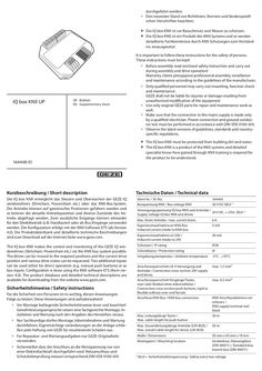
Beiblatt IQ box KNX UP
… sheet XX XX 164448-01 Kurzbeschreibung / Short description The IQ box KNX must be protected from building dirt and water. The IQ box KNX is a product of the KNX systems and detailed specialist know-how gained through KNX training is required for the product to be understood. Technische Daten / Technical data Die IQ box KNX ermöglicht das Steuern und Überwachen der GEZE IQ windowdrives (Slimchain, Powerchain etc.) über das KNX-Bus-System. Die Antriebe können auf gewünschte Positionen gefahren werden und es können die aktuelle Antriebsposition und diverse Zustände des Antriebs abgefragt werden. Zwei zusätzliche Eingänge können entweder für den Direktbetrieb (z.B. Handtaster) oder als Bus-Eingänge verwendet werden. Die Konfiguration erfolgt mit der KNX-Software ETS (ab Version … ). The product database and detailed technical descriptions are available for downloading from the website www.geze.com. Sicherheitshinweise / Safety instructions Für die Sicherheit von Personen ist es wichtig, diesen Anweisungen Folge zu leisten. Diese Anweisungen sind aufzubewahren! àà Vor Montage beiliegende Sicherheitshinweise lesen und beachten! Gewährleistungsansprüche setzen eine fachgerechte Montage, Installation und Wartung nach den Angaben des Herstellers voraus. àà Nur Sachkundige dürfen Montage, Inbetriebnahme und Wartung durchführen. Eigenmächtige veränderungen an der Anlage schließen jede Haftung von GEZE für resultierende Schäden aus. àà Für Reparatur- und Wartungsaufgaben nur GEZE-Originalteile verwenden. àà Sicherstellen dass der Anschluss an die Netzspannung nur von einer Elektrofachkraft durchgeführt wird. Netzanschluss und Schutzleiterprüfung müssen entsprechend DIN VDE 0100-610 Versorgungsspannung IQ box KNX und Antriebe / 24 V DC, +-25%, SELV *) Supply voltage IQ box KNX and drives Max. Strom Antriebe / max. current drives 6A Eigenstromaufnahme an KNX-Bus Induced current intake to KNX-bus
(PDF | 585 KB)
Schiebewandsystem MSW MSW mit VerbundSicherheitsglas (VSG)
… Product liability … Schiebewandsystem MSW / MSW sliding wall system Symbole und Darstellungsmittel / Symbols and means of representation Warnhinweise / Warnings In dieser Anleitung werden Warnhinweise verwendet, um Sie vor Sach- und Personenschäden zu warnen. XX Lesen und beachten Sie diese Warnhinweise immer. XX Befolgen Sie alle Maßnahmen, die mit dem Warnsymbol und Warnwort gekennzeichnet sind. In these instructions, warnings are used to warn against material damage and injuries. XX Always read and observe these warnings. XX Observe all the measures that are marked with the warning symbol and warning word. Warnsymbol Warnwort Bedeutung / Meaning Warning Warning word symbol Gefahren für Personen. vorsicht Nichtbeachtung kann zu leichten Verletzungen führen. Danger for persons. CAUTION Non-compliance can result in minor injuries. Symbole und Darstellungsmittel / Symbols and means of representation Um die korrekte Bedienung zu verdeutlichen, sind wichtige Informationen und technische Hinweise besonders herausgestellt. Important information and technical notes are emphasised in order to illustrate the correct operation. Symbol Bedeutung / Meaning bedeutet „Wichtiger Hinweis“ means “important note” bedeutet „Zusätzliche Information“ means “additional information” XX XX Symbol für eine Handlung: Hier müssen Sie etwas tun. XX Halten Sie bei mehreren Handlungsschritten die Reihenfolge ein. Symbol for an action: Here you have to do something. XX Observe the sequence if there are several action steps. Produkthaftung / Product liability Gemäß der im Produkthaftungsgesetz definierten Haftung des Herstellers für seine Produkte sind die in dieser Broschüre enthaltenen Informationen (Produktinformationen und bestimmungsgemäße Verwendung, Fehlgebrauch, Produktleistung, Produktwartung, Informations- und Instruktionspflichten) zu beachten. Die Nichtbeachtung entbindet den Hersteller von seiner Haftungspflicht. In accordance with the liability of manufacturers for their products as defined in the German “Produkthaftungsgesetz” (Product Liability Act), the information contained in this brochure (product information and proper use, misuse, product performance, product maintenance, obligations to provide information and instructions) is to be observed. Non-compliance releases the manufacturer from its statutory liability. Abkürzungen / Abbreviations ESG VSG Einscheiben-Sicherheitsglas Verbund-Sicherheitsglas Toughened safety glass Laminated safety glass … Schiebewandsystem MSW / MSW sliding wall system Mitgeltende Dokumente / Additional applicable documents XX Beachten Sie die Sicherheitshinweise Mat. Nr. 160443 XX Observe the safety instructions Mat. No. 160443 Montageanleitung MSW Schiebetüren, Drehtüren, Anschlagtüren, Pendeltüren, Festfeld (DE/GB) 138026 Montageanleitung MSW Schiebebedarfstüren (DE/GB) 138027 Verklebeanleitung GEZE MSW 133073 Sicherheitsdatenblatt Klebstoff Mounting instructions for MSW sliding doors, swing doors, single action doors, double action doors, fixed panels (DE/GB) 138026 Mounting instructions for MSW sliding requirement doors (DE/GB) 138027 GEZE MSW bonding instructions 133073 Safety data sheet for adhesive
(PDF | 1,014 KB)
Slimdrive EMD-F/R integrierter Rauchschalter
… Product liability … 22 10 Technische Daten / Technical data … Produkthaftung / Product liability Gemäß der im Produkthaftungsgesetz definierten Haftung des Herstellers für seine Produkte sind die in dieser Broschüre enthaltenen Informationen (Produktinformationen und bestimmungsgemäße Verwendung, Fehlgebrauch, Produktleistung, Produktwartung, Informations- und Instruktionspflichten) zu beachten. Die Nichtbeachtung entbindet den Hersteller von seiner Haftungspflicht. In compliance with the liability of the manufacturer for his products as defined in the German “Product Liability Act”, compliance with the information contained in this brochure (product information and intended use, misuse, product performance, product maintenance, obligations to provide information and instructions) must be ensured. Failure to comply releases the manufacturer from his statutory liability. … „Elektrische Anlagen und Betriebsmittel“ Das Produkt sollte so eingebaut oder verbaut werden, dass ein müheloser Zugriff auf das Produkt bei etwaigen Reparaturen und/oder Wartungen mit verhältnismäßig geringem Aufwand gewährleistet ist und etwaige Ausbaukosten nicht in einem wirtschaftlichen Missverhältnis zu dem Wert des Produkts stehen. à The mandatory installation, maintenance and repair work must be performed by properly trained personnel authorised by GEZE. à The country-specific laws and regulations are to be observed during safety-related tests. à If unauthorised changes are made to the system, GEZE cannot be held liable in any way whatsoever for any resulting damage, and the statement of approval for use in escape and rescue routes is no longer valid. à GEZE does not accept any warranty for combinations with third-party products. à Furthermore, only original GEZE parts may be used for repair and maintenance work. à The connection to the mains voltage must be made by a professional electrician. Perform the power connection and protective earth connection test in accordance with VDE 0100 Part 610. à Use an on-site automatic cut-out as the line-side disconnecting device, the dimensioning of which is matched to the type, cross-section, type of routing and ambient conditions of the on-site power supply circuit. The automatic cut-out must have at least … “Electrical installations and equipment” The product should be installed or incorporated in such a way that effortless access to the product is guaranteed during any repairs and/or maintenance, and that any removal costs do not stand out of economic proportion to the value of the product. … Slimdrive EMD-F/R Erdungskabel anschließen / Connecting the earthing cable à Angaben für den elektrischen Anschluss müssen dem Anschlussplan (Id. 142194) entnommen werden. à Anweisungen zur Erdungsverkabelung müssen dem Beiblatt Erdungsverkabelungen (Id. 123304) entnommen werden. à The specifications for the electrical connection have to be taken from the wiring diagram (Id. 142194). à Instructions for earthing cabling must be taken from the supplementary sheet on earthing cabling (ID 123304). X Erdungsbohrung gemäß Zeichnung in die Haube bohren. X Drill an earthing hole into the cover in accordance with the drawing. 15 A Erdungskomponenten wie dargestellt montieren. X Install the earthing components as shown. X Erdungskabel (1) gem. Beiblatt Erdungsverkabelungen (Id. 123304) an Geräteflachstecker (2) anschließen. X Connect the earthing cable (1) in accordance with supplementary sheet earthing cabling (ID 123304) to the device flat plug (2). Ø … s GREEN). 10 22 Technische Daten / Technical data Betriebsspannung Stromaufnahme Ausgang Feststellvorrichtung Zusatzmelder EMV Störfestigkeit EMV Störaussendung Haushaltsklasse Schutzklasse 24 V DC ± 10 % max. 260 mA 24 V DC ± 10 % max. 200 mA 24 V DC ± 10 % max. 60 mA für externe Rauchschalter entsprechend EN 50130-4 entsprechend EN 55022/B EN 55022/A Industrieklasse IP20 – nur für trockene Räume Operating voltage Current consumption Output hold-open device Additional detector EMC immunity from disturbance EMC emitted interference Household class Degree of protection 24 V DC ± 10% max. 260 mA 24 V DC ± 10% max. 200 mA 24 V DC ± 10% max. 60 mA for external smoke switch in accordance with EN 50130-4 in accordance with EN 55022/B EN 55022/A industrial class IP20 – only for dry areas Slimdrive EMD-F/R Wartung-Pflege-Reparatur / Maintenance-care-repair 23 Germany GEZE GmbH Niederlassung Süd-West Tel. +49 (0) 7152 203 594 E-Mail: leonberg.de@geze.com GEZE GmbH Niederlassung Süd-Ost Tel. +49 (0) 7152 203 6440 E-Mail: muenchen.de@geze.com GEZE GmbH Niederlassung Ost Tel. +49 (0) 7152 203 6840 E-Mail: berlin.de@geze.com GEZE GmbH Niederlassung Mitte/Luxemburg Tel. +49 (0) 7152 203 6888 E-Mail: frankfurt.de@geze.com GEZE GmbH Niederlassung West Tel. +49 (0) 7152 203 6770 E-Mail: duesseldorf.de@geze.com GEZE GmbH Niederlassung Nord Tel. +49 (0) 7152 203 6600 E-Mail: hamburg.de@geze.com GEZE Service GmbH Tel. +49 (0) 1802 923392 E-Mail: service-info.de@geze.com Austria GEZE Austria E-Mail: austria.at@geze.com www.geze.at Hungary GEZE Hungary Kft. E-Mail: office-hungary@geze.com www.geze.hu Scandinavia – Denmark GEZE Danmark E-Mail: danmark.se@geze.com www.geze.dk Baltic States GEZE GmbH Baltic States office E-Mail: office-latvia@geze.com www.geze.com Iberia GEZE Iberia S.R.L. E-Mail: info@geze.es www.geze.es Singapore GEZE (Asia Pacific) Pte, Ltd. E-Mail: gezesea@geze.com.sg www.geze.com Benelux GEZE Benelux B.V. E-Mail: benelux.nl@geze.com www.geze.be www.geze.nl India GEZE India Private Ltd. E-Mail: office-india@geze.com www.geze.in South Africa GEZE South Africa (Pty) Ltd. E-Mail: info@gezesa.co.za www.geze.co.za Italy GEZE Italia S.r.l E-Mail: italia.it@geze.com www.geze.it Switzerland GEZE Schweiz AG E-Mail: schweiz.ch@geze.com www.geze.ch GEZE Engineering Roma S.r.l E-Mail: roma@geze.biz www.geze.it Turkey GEZE Kapı ve Pencere Sistemleri E-Mail: office-turkey@geze.com www.geze.com Bulgaria GEZE Bulgaria - Trade E-Mail: office-bulgaria@geze.com www.geze.bg China GEZE Industries (Tianjin) Co., Ltd. E-Mail: chinasales@geze.com.cn www.geze.com.cn GEZE Industries (Tianjin) Co., Ltd. Branch Office Shanghai E-Mail: chinasales@geze.com.cn www.geze.com.cn GEZE Industries (Tianjin) Co., Ltd. Branch Office Guangzhou E-Mail: chinasales@geze.com.cn www.geze.com.cn GEZE Industries (Tianjin) Co., Ltd. Branch Office Beijing E-Mail: chinasales@geze.com.cn www.geze.com.cn France GEZE France S.A.R.L. E-Mail: france.fr@geze.com www.geze.fr GEZE GmbH Reinhold-Vöster-Straße 21–29 71229 Leonberg Germany Tel.: 0049 7152 203
(PDF | 4 MB)
PERLAN 140 Manuelle Schiebesysteme
… Product information … 21 Symbols and markings This instruction manual uses warning notices which help You to avoid damage to persons or material. u Always read and observe these warning notices! u Follow all the instructions that are given in a warning notice. Warning sign Warning word Description Danger for persons. WARNING Non-observance may lead to death or serious injuries. To point out the correct usage, important information and technical notices are emphasised. Sign Description symbolizes „Important Notice“ symbolizes „Additional Information“ u Sign for an action: This tells You what has to be done. When there are multiple steps, observe their sequence. Product liability Your attention is drawn to the “product liability law“ defined liability to the manufacturer for his products which are contained in the main catalogue (product information, usage, misuses, product activity, product maintenance, the duty to inform and the duty to instruct). Non-compliance with these conditions relieves the manufacturer from any liability. 12 PERLAN 140 … Personnel qualification The mounting and installation instructions list persons as well as the minimum qualification required by them to carry out the work described: ú Users Persons who have no personnel qualification but nevertheless come into contact with the product. ú Personnel Persons whose qualification entitles them to carry out the work described. The designation of the work carried out is often given, for example „Maintenance personnel“. ú Technicians Personnel of a company that carries out mounting or installation of the product. ú Operators Also called end users. The operator may not be the owner of the product (for example the property management). … Product information … .1 Product information for sliding door gears In accordance with the liability of the manufacturer defined in Section … of the German “Produkthaftungsgesetz” (Product Liability Act - ProdHG) for his products the following information on sliding door gear has to be observed. Non-observance releases the manufacturer from his statutory liability. Product information and proper use Sliding door gears in this definition are gears for sliding leaves and similar sliding elements, called “objects” below, that are usually not moved faster than at walking speed. Sliding door gears are used at perpendicularly mounted leaves made of wood, plastic, glass, aluminium or steel and their corresponding material combinations. A guide is provided at the lower horizontal sides of the leaves. The products designed for shading equipment are corrosion resistant special versions. Proper use includes in particular proper mounting. The gear has to be sufficiently stable at all positions. Functioning of the gear may not be impaired or modified by mounting. A buffer has to be used in the leaf middle to limit the movement. The Perlan 140 AUT may not under any circumstances be used in passage areas or other areas that have a high occurrence of persons. Outdoors the drive unit of the Perlan AUT has to be mounted so that it is not exposed directly to weather influence. Misuse Misuse – meaning any use that is not the proper use – of sliding door gears exists in particular when ú the gears are used with a higher load than the maximum bearing capacity that is specified in the catalogue and in the remaining product documentation, ú improper mounting or insufficient fastening has taken place, ú particularly aggressive media can act on them, ú inappropriately rough bump and fall loads act on them, ú the position of the channel rail deviates too strongly from the horizontal, ú foreign material penetrates the track, ú the rollers are used with excessive speed, ú modifications were carried out that were not agreed with the manufacturer, ú obstructions are inserted into the opening area or between the leaves or the object respectively, thus preventing its proper use, ú additional loads act on leaves or the object, ú if there is an intervention between the leaf and the masking frame when being pushed closed or when closing or if a person or a body part is located within this area when the leaf is pushed closed. Sliding shutters are not a substitute for devices specially designed as burglary prevention devices. 13 Safety PERLAN 140 Any use that does not conform to the “Proper use” and does not conform to the technical specification is an improper use. Warranty claims cannot be asserted for any damage that is not proper use or constitutes improper use. Product performance In as far as the product performance is not specified in concrete forms in our catalogues, brochures, technical specifications and other product instructions, the requirements placed on our fittings have to be agreed with us. Our regulations dealing with the assembly of the fittings are binding. Product care and maintenance Safety-oriented fittings have to be checked regularly for firm seating and wear. Depending on the requirements, the fixing screws are to be tightened or replaced respectively. In addition, the following service and maintenance work has to be carried out at least once a year: ú Check the functionality of all the moving parts. ú Use only such detergents that do not impair the anti-corrosion protection of the fittings. ú Replace defective fittings. ú Adjusting work at the fittings as well as the exchange of the fittings have to be carried out by a specialist company. ú Plastic rollers may not be greased. Duties to provide information and instructions The following means are available to the planner, the specialised trade, the technicians, the builder-owner and the user in order to fulfil the duty to provide information and instructions: ú Catalogues, brochures ú Specification texts, bidding documents ú Installation and mounting instructions, installation drawings In order to ensure the correct use, to ensure the function and the maintenance and care of the fittings ú architects and planners are required to request and observe the necessary product information, ú the specialised trade is required to request and observe the product information and instructions in the price lists, and in particular to request all required instructions and pass these on to the technicians, ú all the technicians are required to observe all the product information and to pass it on to the contractors and users. … .2 Basic safety principles Fundamental dangers Dangerous voltages: The Perlan 140 AUT is operated with a dangerous voltage. Mounting, disassembly and connection work of the operating button and the drive may only be carried out by authorised persons using the designated tools. Before beginning any work the power supply is to be switched off and to be secured against unauthorised restarting. Safety measures ú Availability of the operating manual: The operating manual has to be kept directly next to the GEZE product and made available to the personnel unsolicited. ú Availability of the mounting instructions: The mounting instructions are to be retained by the responsible technician or maintenance personnel. These are responsible for the correct mounting as well as maintenance of the system. ú Removal of protective devices: No protective device may be disassembled or put out of action. The only exception is formed by the authorised service personnel. Normal operation after servicing work may not be carried out until after all the protective devices have been mounted and checked. Power connections The Perlan AUT may only be connected as specified in the technical data sheets. It must be possible for the customer to switch off all the power connections. 14 PERLAN 140 General Spare parts Solely original GEZE spare parts may be used for maintenance and repair work. Modifications Any modification whatsoever (additions and/or alterations) to a GEZE product requires written confirmation by the manufacturer. EC conformity All the GEZE products are designed and built in accordance with the latest safety standards. Additional analyses have not been carried out for this reason. The maximum displacement force of the Perlan AUT is so low that any danger of injury can be excluded. Standards The following guidelines and standards were taken into consideration when developing and designing the Perlan range: EN 1527; EN 1670
(PDF | 2 MB)
Inbetriebnahmekoffer IQ windowdrives
… Product liability … Technical data … 40 IQ windowdrive Symbols and illustrations In order to illustrate proper operation, important information and technical information is highlighted. Symbol Meaning means "important information"; Information on avoiding material damage, understanding a concept or optimising the operation sequences means “additional Information” X Symbol for an action: there is something you must do here. X If there are several actions to be taken, keep to the given order. Product liability In compliance with the liability of the manufacturer for his products as defined in the German "Product Liability Act", compliance with the information contained in this brochure (product information and intended use, misuse, product performance, product maintenance, obligations to provide information and instructions) must be ensured. Failure to comply releases the manufacturer from their statutory liability. Validity à à à à Valid from software version V3.2 for Slimchain 24 V, Powerchain, E 250 NT Valid from software version V3.1 for für Slimchain 230 V Valid from software version V1.0 for F 1200+ Valid from software version V1.0 for IQ box Safety Scope of delivery Service case, completely packed, Mat. No. 142586 Contents Service case Mains connection cable Connection cable drive – Service case User manual “Parameterization of IQ windowdrive” Carrying strap Replacement fuse … Intended use The service terminal ST 220 and the service case are used to set all the parameters and functions of IQ windowdrive and the IQ box Safety. Any other use than the intended use as well as all changes to the product are not permissible. … Safety notices à The mandatory installation, maintenance and repair work must be performed by properly trained personnel authorised by GEZE. à The country-specific laws and regulations are to be observed during safety-related tests. à GEZE shall not be liable for injuries or damage resulting from unauthorised modification to the service terminal ST 220. à GEZE provides no warranty in the event of combinations with third-party products. à Repairs must be carried out by a repair workshop authorised by GEZE. à Only original GEZE parts may be used for repair and maintenance work. à Improper use outside the manufacturer's specification can impair device safety. Applications other than specified by the manufacturer may compromise the safety of the device. Replace battery In case of replacement, the battery may only be replaced with an equivalent battery: à GEZE rechargeable battery set 2×12 V; … Technical data Technical data Electrical data and connection values Mains voltage Frequency Rated current consumption Output voltage Output current Battery capacity Degree of protection according to DIN EN 60529 Protection type according to DIN EN 61140 Operating temperature range 100–240 V AC 50 … Notes on commissioning X à à à à à Commissioning Before connection, make sure the DIP switch on the drives (solo/master/slave) is set correctly as otherwise the data will not be able to be read and cannot be changed (refer to the IQ windowdrive wiring diagram). Only the master can communicate with the ST 220. If a slave is connected to the ST 220, no text appears on the display. The locking drives Powerlock E 905 and E 906 must be connected to the device in connection with a chain drive or spindle drive for the data to be read out. Drive settings via the service terminal ST 220 can only be made when the drives are in their end positions. If drives are connected in a synchro-network, they must be connected to the service case in compliance with the wiring diagram (see the wiring diagram IQ windowdrive for the circuit diagram). A drive must be connected to the IQ box Safety to parameterize it. à Drives in a synchro-network can only be checked together, a drive set to „Slave“ cannot be operated separately. … Drives which can be configured are displayed Inputs Positions Obstruction information Cycles Internal values Distance travelled Operating Duration Messages Data Data Analyser LIN Current cycle Last cycle Delete current Delete old Drive Control Factory setting Teaching Language IQ box Safety 32 YES/NO YES/NO German/English Change to IQ box Safety Menü Menu level … Diagnosis Information Inputs Current Value Signals [V] Supply [V] Brightness[V] Current States Turn blockage current. Pos. [um] (Hallsensor) abs. Pos. [um] (Absolute position sensor) HSK Pos. [mm] (Position Main closing side) Pos. [mm] Drive direction Tilt/Turn Tilt open (End pos.) Tilt close (End pos.) Block open. (End pos.) Block close. (End pos.) Cal. (End pos.) Turn open (End pos.) Positions Obstacle info Cycle Counter Internal Value Moved Distance Operation Time DataAnalyser LIN Log Messages Data Current cycle Last cycle Erase current Erase last Drive Stop Mode Control Unit Factory Settings Calibration Sure? Yes Sure? No Drive Light Sensor Language IQ box Safety 34 German English Change to IQ box Safety Menü Cal. prox.1 Cal. prox.2 Cal. prox.3 Cal. pos. Connected Drive Moved Distance [m] Connected Drive Operation Time [h] active inactive Type Serial number Type Serial number HW-Revision SW-Version Sure? Yes Sure? No Sure? Yes Sure? No see chapter … .4 LO parameter speed The parameter speed describes the speed with which the locking drive locks or unlocks. The LO parameter speed can be set within the range MIN – MAX. The setting for this data has no influence on the unlocking speed in case of an alarm. This always occurs at maximum speed.
(PDF | 867 KB)